Mark 10 Dimming Ballast Wiring Diagram
Dimming Ballasts Wiring Electrical 101

Awesome Wiring Diagram Downlights Diagrams Digramssample

Gfci Receptacle And Switch Same Box Home Electrical Wiring

New Legrand Dimmer Switch Wiring Diagram Diagramsample

Dimming Ballast Wiring Diagram Wiring Diagram

Rz 8869 277v Fluorescent Emergency Ballast Wiring Diagram 277v

Hunt control systems inc.
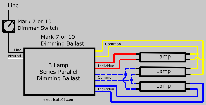
Mark 10 dimming ballast wiring diagram. A wiring diagram is a streamlined standard photographic representation of an electric circuit. The following lutron dimmers have been tested to provide the proper control voltages for advance mark vii 0 10v electronic dimming ballasts and advance mark x powerline dimming ballasts. 800 x 600 px source. Mark 10 powerline electronic dimming ballasts make converting your existing fixtures easy.
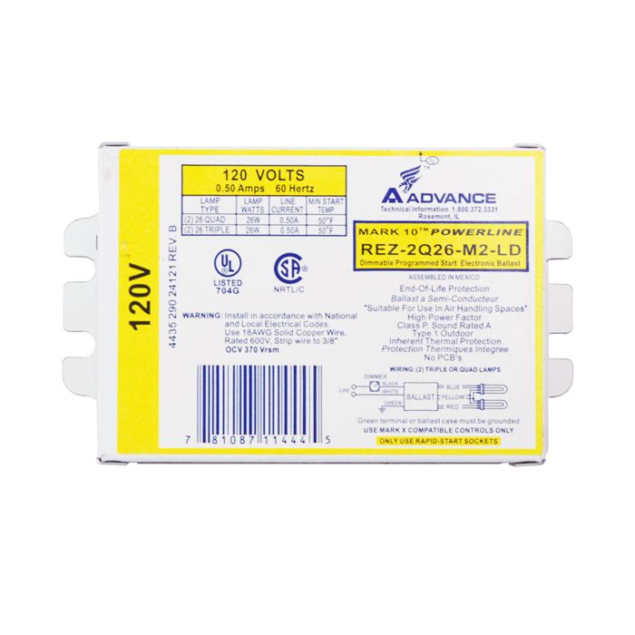
Mark 10 powerline ele dim ballast 2 42w cfl 4 pin v simply 1 replace the ballast 2 replace the switch 3 dim the lights that is all it. Dimming fluorescent lights are usually found in commercial and institutional environments and not common in the household. Here are some of the leading drawings we receive from different sources we really hope these pictures will certainly work to you and hopefully very appropriate to exactly what you desire regarding the lutron dimming ballast wiring diagram is. Browse the mark 10 powerline products and find the product that you are looking for by using the compare simply 1 replace the ballast 2 replace the switch 3 dim the lights that is.
Lutron maestro 3 way dimmer wiring diagram ariadni toggler at size. Philips advance mark 10 powerline dimmable ballasts wiring. Please refer to the instruction sheets and specification submittals for any settings or calibration requirements necessary for the lutron dimmers to provide. The advance mark 10 ballast generates a modified powerline phase cut control signal which is in turn controlled by a.
Cfq18w g24q 18w cfl quad tube lamp pl c18w 4p f18dbx 4p cf18dd e. Refer to page for ballast dimensions and page wiring diagram. Advance mark 10 rez2s32sc t8 dimming ballast iballastrhiballast. It shows the elements of the circuit as simplified shapes and also the power and also signal connections in between the devices.
Dimming ballasts are available for fluorescent tubes and cfls that use an external ballast. 2 120 277 izt 2s54 d 98 18 0 80 0 03 10 0 82 50 10 d 56a mark 7 0 10v ballasts for 14 28w t5 lamps programmed start. Variety of 0 10v dimming ballast wiring diagram. These ballasts are usually rapid start or programmed start and have a good dimming range.
Output and greater than 0 90 throughout the dimming range for primary lamp. Wiring diagram input power ansi watts ballast factor thd line current amps f14t5 14w.

Lutron 3 Way Switch Wiring Diagram Volovets Info With Images

55 Chevy Color Wiring Diagram Chevy Diagram 55 Chevy

Wiring Diagram Fan Light Source At The Fixture Ceiling Fan With

The 8 Best Ac Wiring Diagram Samples Thermostat Wiring Ac

Luxury Wiring Diagram Of An Alternator Diagrams Digramssample

Pin On Three Way Switch

Best Of Wiring Diagram For Fog Lights Without Relay Diagrams

New Imo Contactor Wiring Diagram

Ge 15312 3 Way Circuit 6 60 Jpg 857 986 With Images House

Advance Dimming Ballast Wiring Diagram Kuiyt 10balmoond
Mark X Ballast Wiring Diagram Wiring Diagram

Details About Tanning Bed Ballast Universal Triad 493b2

82251 Ford 600 Tractor Wiring Diagram Wiring Resources
