Mark 10 Ballast Wiring Diagram

Led Fluorescent Tube Wiring Diagram With Images Led

Awesome Wiring Diagram Downlights Diagrams Digramssample
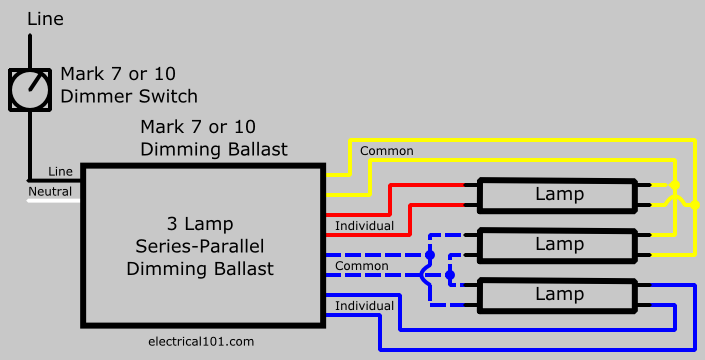
Dimming Ballasts Wiring Electrical 101

Tube Wiring Diagram With Images T8 Led Tube Led Tubes T8 Led

New House Electrical Wiring Basics Diagram Wiringdiagram

Metal Halide Ballast Wiring Diagram With Images Diagram

Mark 10 powerline ballasts for linear 5 full range continuous dimming t5ho to 1 for ballast dimensions and wiring diagrams see page 5.
Mark 10 ballast wiring diagram. So how to wire the new ballast to my fixture so it works. Using advance mark 7 or mark 10 dimming ballast and dimmer switch. Assortment of fluorescent ballast wiring diagram. 16 lamp wiring diagrams 19 ballast control types 20 ecosystem ballasts 22 emergency backup ballast 24 ballast.
Philips advance mark 10 powerline dimmable ballasts wiring. Advance s mark 7 v ballasts are 5 full range continuous dimming t5 ho to 1 for ballast dimensions and wiring diagrams see page 3. Mark 10 powerline ele dim ballast 2 42w cfl 4 pin v simply 1 replace the ballast 2 replace the switch 3 dim the lights that is all it. I suspect the wiring is not as simple as described.
Cfq18w g24q 18w cfl quad tube lamp pl c18w 4p f18dbx 4p cf18dd e. Follow the colore coded wiring diagram was the recommendation yet after connecting all like colors on the new ballast to the fixture all i got was a delayed dim light at the base of each fluorescent bulb. Changing the wiring on a fluorescent light fixture from series to parallel involves changing the ballast from a series to a compatible parallel ballast. A wiring diagram is a streamlined standard pictorial representation of an electric circuit.
Please refer to the instruction sheets and specification submittals for any settings or calibration requirements necessary for the lutron dimmers to provide. Dimming ballast wiring diagrams 2 lamp dimming ballast wiring diagram. Parallel ballasts can only be wired in parallel according to the diagram on the ballast. 1 lamp rapid start ballast diagram.
It reveals the components of the circuit as streamlined forms and the power and also signal links in between the gadgets.

Led Tube Wiring Diagram With Images Led Tubes Fluorescent

T8 Led Tube Wiring Diagram Led Fluorescent Led Fluorescent Tube

Two 2 Lamp Series Ballast Wiring Diagram With Images Ballast

Rz 8869 277v Fluorescent Emergency Ballast Wiring Diagram 277v

Ignition Coil Distributor Wiring Diagram

Tube Light Connection Circuit Wiring Diagram Electrical4u

Electronic Ballast Circuit Progetti Progetti Da Provare

Pin By Thanglenchonbaldu Chongloi On Electric Electrical Wiring

Wiring Diagram Of Samsung Microwave Oven With Images Microwave

Pin By A Joe Petrucce On Electronic Projects Electronics

Sign Ballasts Smart Wire Parallel Wire Keystone Technologies

New Imo Contactor Wiring Diagram

07 08 350z Nissan 09 370z Xenon Hid Headlight Ballast Z Oem
